Another type of aquaponic system that is used both commercially and on home scale is the constant flow aquaponic system. There are both advantages and disadvantages to using this type of system over a traditional ebb & flow system, the choice is left up to the farmer. Some farmers swear by the constant flow system as it requires less maintenance, however this is not always the truth, as it does require that you supply ample amount of oxygen to the tank for both the fish and vegetables.
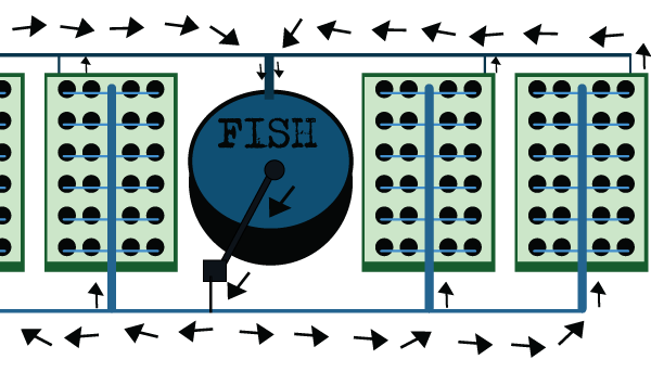
The graphic below shows a single grow bed designed for using without a grow medium. These beds are flooded to an approximate depth of 12 inches and flowing continuously from and to the fish tank. The plants are secured in a floating platform with the roots extending directly into the water. With this system, you need to make sure the water is properly aerated to give the plants sufficient oxygen to the roots.

You can check out a system like this being used in a full scale commercial production at the following link:
AERATION FOR CONSTANT FLOW SYSTEMS
The following Information was provided via DIY Aquaponics. These guys are great, I would totally recommend that you check out their website for more information.
“Building an air flow aeration system is a little labor intensive to build. I don’t mean difficult though, just time consuming, but it can’t be beat for creating bubbles over a wide area and oxygenating the water. Basically it is very simple.
For this system you can use an air pump or large commercial oil-less air compressor (which ever you use, it must to be oil-less). It is recommended that the air be pumped through a high pressure copper tubing supply line. A regulator outlet valve can be attached and used to provide a lower air pressure to a 2 inch PVC manifold leading to the inflow end of the fish tank.
From the manifold, a piece of 1 inch PVC tubing is extended about 10 inches out over the edge of the fish tank and elbowed at a 90° angle toward the bottom of the tank. Another 90° elbow is installed at the end and another piece of 1 inch PVC is then run across the bottom of the tank. It sits about 2 inches from the bottom of the tank and running from one side of the inflow end of the tank to the other and a capped is installed on the end.
That portion of the tube is where the actual intensive labor comes in. Before it is installed, naturally, to create this section, draw straight lines at 1/4 inch intervals around the 1 inch PVC from one end to the other; then mark them at 1/4 inch increments from one end to the other and draw a line around the tubing at each mark. Using a 1/32 inch drill bit, drill tiny pin-holes where each of the lines intersects. It is permissible to even drilled holes in the end cap just for good measure. I mean why not, it was there!
This is the difficult part as the drill bit is hardly larger than a needle. A larger pin hole can be created using a 1/8 inch bit if desired, but the smaller holes create a much finer stream. Suffice it to say, it is possible you will break a number of bits before you finished. However, the results are well worth the effort. A study stream of foam like bubbles can be created which can actually cause the water to boil up at least 1 to 1 ½ inches above the water level of the tank all across the end of the tank.
A note of caution to prevent problems later, always remember, after the holes are drilled, you must make sure there are no obstructions in the holes and also clean out the inside of the tube carefully removing all filings. A possible solution is the use of a heavy grit piece of sandpaper wrapped and tacked around a wooden dowel and rammed through the PVC. Then use a high pressure air nozzle to insure no bits or pieces of the drilling process were left to later block the air holes.


